Editing Disk Bay Layouts
To create or edit current Disk Bay Layout select in the menu or use a shortcut .
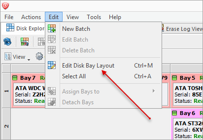
This will bring you to the Disk Bays Layout View where you can manipulate, save, import and create Disk Bay Layouts.
- Free Grid Layout allows user to place Disk Bay widget at any position, change Bay widget size and its alignment (vertically or horizontally) individually for each Bay. Hence, user can create relatively accurate mocking layout of actual (physical) disk Bay slots located on hardware chassis
- Table Layout is similar to Disk Bay Layout from previous versions. However, now user can re-size or select Disk Bay widgets by using row and column headers
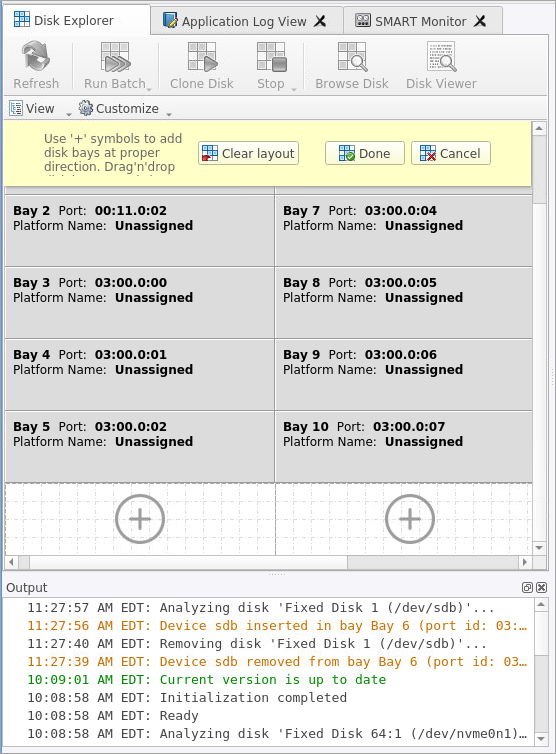
Creating a new layout
To create a new layout select either >Free Grid or Table layout option and start adding Disk Bays using circled "+" symbols.
If predefined layout already exists click Clear Layout to remove it and create a new one.
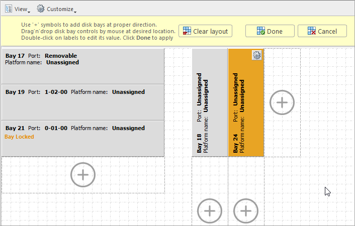
Editing Disk Bay layout
- Click on circled “+” signs to add new Disk Bay widget on a side of existing one. New Disk Bay widget size will be corresponded to adjusted Disk Bay
- To re-size Disk Bay use mouse to drag it's right side or bottom
- To set Disk Bay vertically-oriented use mouse to drag it's right side to shrink it until it changes to vertical state.
- To delete Bay(s) select it and press Delete keyboard key or use service menu by clicking “gear” icon on left upper corner
- Use mouse to drag-n-drop selected Disk Bay widgets to new location. If hovered location is invalid Disk Bay widgets will be highlighted with crossed sign
- To change disk label or port, click on corresponded labels on disk widget to start editing
- To change Disk Bay attributes use menu by clicking on “gear” sign on selected Bay
Disk Bay Layout Wizard
To create a new layout using the wizard click . This will launch the Disk Bay Layout Wizard
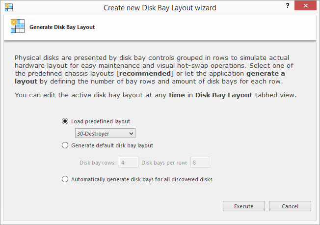
This configuration of a new layout can be done in 1 of 3 ways:
- Load predefined layout
- Here you can find one of our predefined layouts that may fit your system. If an appropriate layout is not listed you may try the next option.
- Generate default Disk Bay layout
- Define your hardware in terms of a disk array arranged in a X by Y grid of disks. You can make adjustments to this later so this may just be a template to start from. Table-style layout will be created.
- Automatically generate Disk Bays for all available physical ports
- Defines your Disk Bay Layout based on the disks recognized by your system's Device Manager. The disks will be placed in their own individual row when the layout is generated.
With the old layout cleared out you now have a new layout ready to be configured to your machine.
Saving and Reverting changes
Click Cancel to revert any changes you made to the layout.